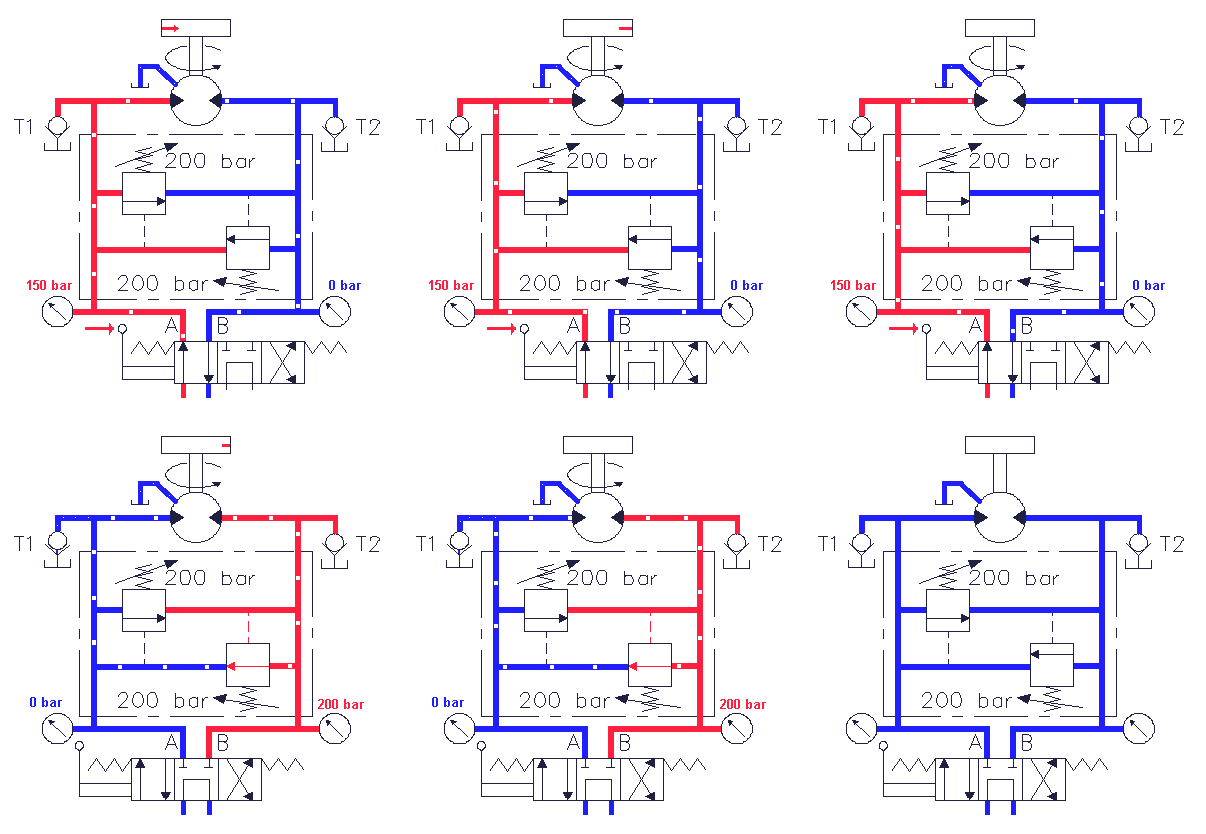
The pressure relief valve in the motor circuit

The diagram shows a hydraulic motor circuit; the direction of rotation of the motor is determined by the position of the 4/3-direction control valve. In the central position of the valve all ports are closed. After activating the left side of the valve, the hydraulic motor starts rotating in the pointed direction.
Generally in hydraulic systems the moment of inertia of the driven load is of a considerable level, so at the moment the 4/3-direction control valve is pushed in the central position the hydraulic motor starts acting as a pump, driven by the load. This will cause a tremendous increase of pressure at the right side of the hydraulic 'motor' and if there was no safety valve, the weakest component would break down or explode! In this system however the pressure relief valve will open and the oil flows back to the left side of the hydraulic motor. Because of the pressure at the right side of the motor the speed of rotation decreases to 0 rpm.
The hydraulic motor has an external leakage line so there will disappear oil from the motorcircuit. This may cause cavitation at the left side of the motor. In this system however the circuit is protected against cavitation by the check valves (suction valves).
The diagram on this page forms a basic diagram for most motor circuits.
