The counterbalance valve is applied as a brake valve on relatively small installations, for example a crane system on a truck, in order to get a positive control on a hydraulic cylinder or motor with a negative load.
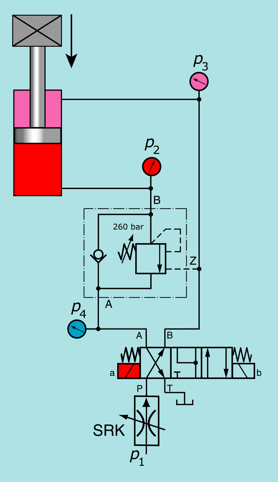
In the hydraulic diagram the counterbalance valve is used to get a positive control while lowering a loaded cilinder.
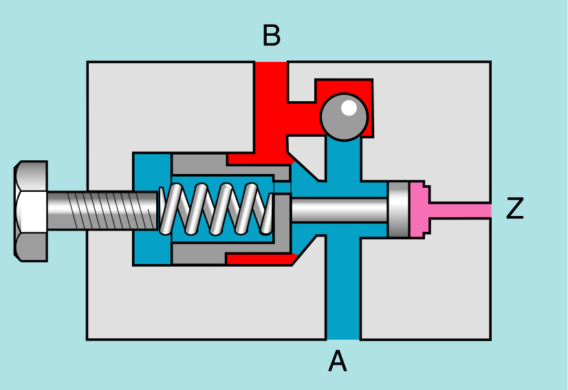
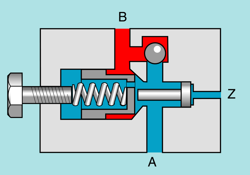
Left: cross section (simplyfied) of a counterbalance valve.
In fact a counterbalance valve is an improved pilot operated checkvalve. An important and major difference between these two valves is:
- the opening pressure of a pilot operated checkvalve depends on the pressure (applied by the load) behind the valve;
- the opening pressure of a counterbalance valve depends on the set spring pressure.
The dynamic performance of a balance valve is many times better than the dynamic performance of a pilot operated check valve
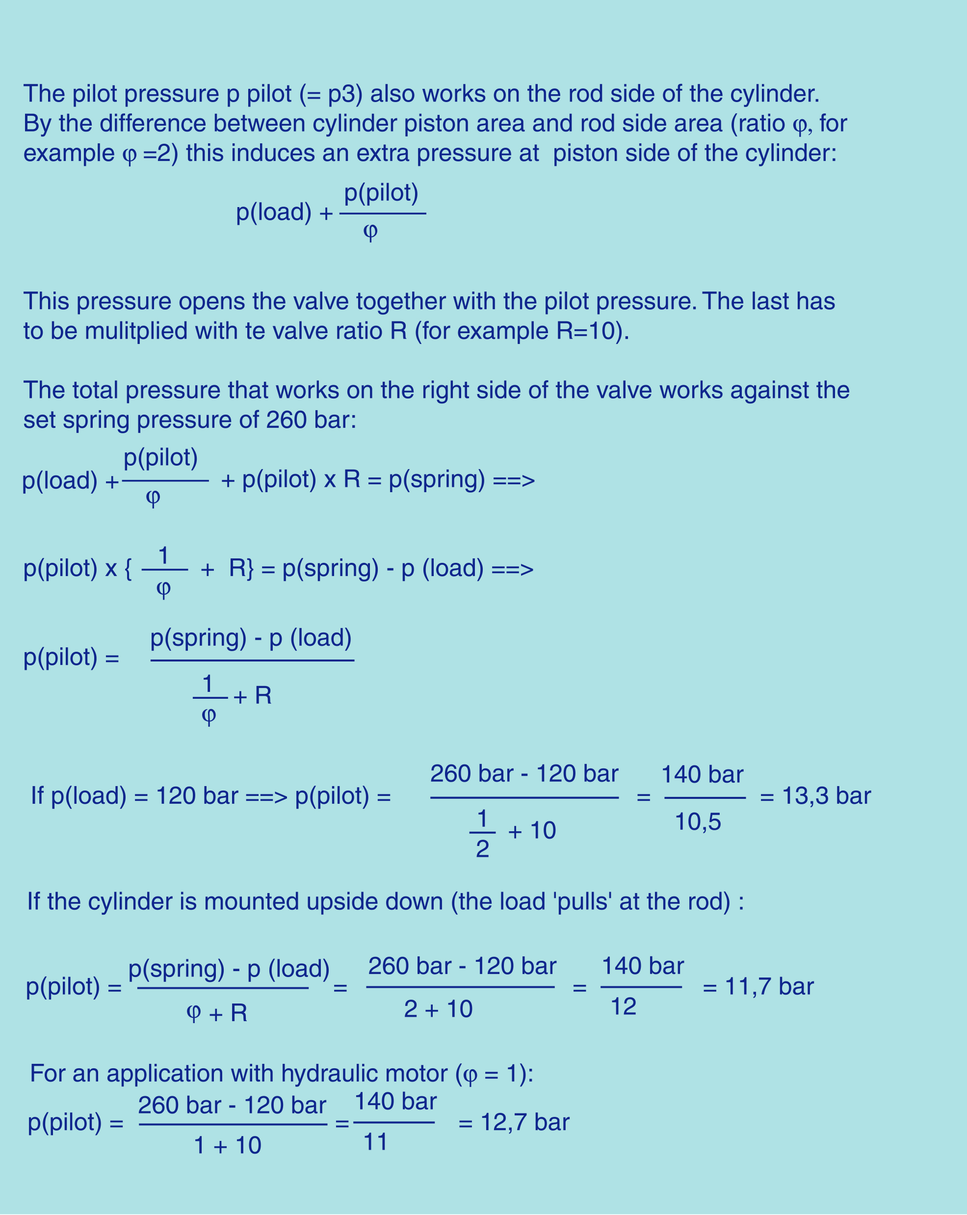
The pilot pressure at Z, required to open the valve in case of an unloaded cylinder depends on the valve pilot ratio R and the pressure setting of the spring. For example if the pressure of the spring is set on 260 bar and the valve has a pilot ratio R=10, the required pilot pressure is 26 bar. If there is a load on the cilinder (load helps opening the valve) the required pilot pressure decreases.
Important:
- A counterbalance valve doesn't control the speed of the lowering cilinder. The speed is determined by the flow which is supplied at the rod side of the cilinder!!
- For best operation, avoid back-pressure at the A port into which the relief spring is usually vented. If there will be back-pressure use an external vented valve.
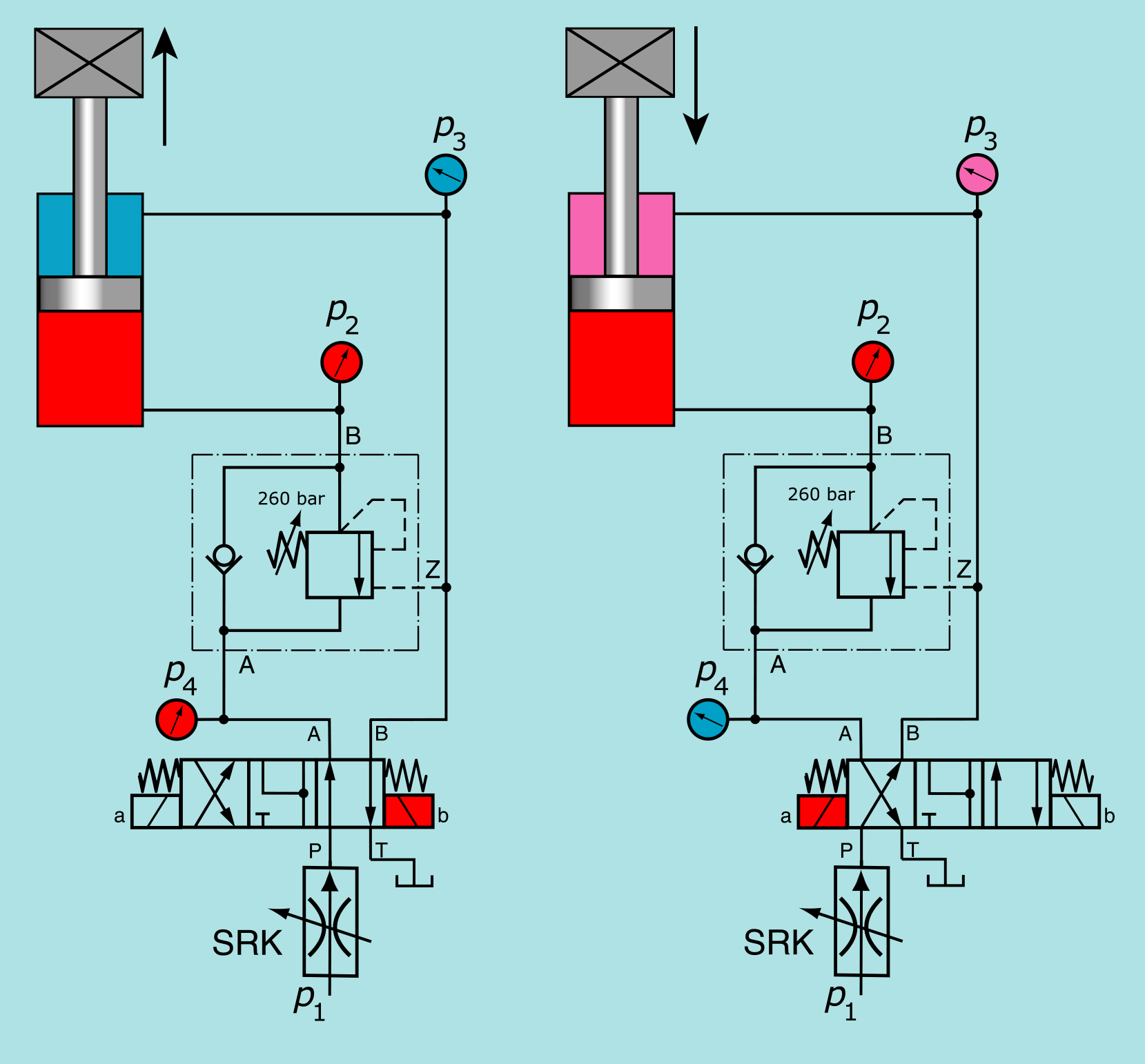
Operation: if the right side of the 4/3-direction control valve is activated the the load will be lifted. The oil flows through the checkvalve which is integrated in the housing of the counterbalance valve.
In order to lower the cylinder, the left side of the 4/3-direction control valve has to be activated. From that moment on pressure is built up at the rod side of the cylinder. This pressure opens the couterbalance valve and the oil at the bottom side of the cylinder flows through the counterbalance valve and the direction control valve back to the reservoir.
As the load helps lowering the cylinder, the cylinder might go down faster than the oil is supplied to the rod side of the cylinder (the cylinder isn't under control at that moment). However, in that case the pressure at the rod side of the cylinder and so the pilot pressure on the counterbalance valve will decrease and the spring moves the counterbalance valve into the direction 'close' as long as it finds a new 'balance'.
If the direction control valve is suddenly put in the middle position while lowering the loaded cylinder, the counterbalance valve closes immediately. This will cause an increase of pressure at the bottom side of the cylinder. However, the counterbalance valve will open at the adjusted pressure and thus protects the cylinder against overpressure!
Pressure setting of the relief function:
The relief section of the valve must have a pressure setting (p spring) high enough in order to be capable to fully re-close the piston in a leak free condition and stop any downstream flow also under maximum load induced pressure (p load).
For this purpose the pressure setting (p spring) must be at least 30% higher than p load:
p spring ≥ 1.3 x p load.
For example: if the maximum load represents 200 bar the countebalance valve should be set at 260 bar.
What's the best pilot ratio R?
High pilot ratio (R ≥ 8 : 1): means that the valve will open at a low pilot pressure. A high pilot ratio allows load lowering with reduced pilot pressure for a faster machine operation and with energy saving. It is best suited for applications where the geometry of the structure maintains the load induced pressures approximately constant during motion (example: extension of a straight boom). If the pressure varies during motion a high pilot ratio may cause an undesired instability of the valve and the installation (poor dynamic performance).
Low pilot ratio (R ≤ 4 : 1): requires a higher pilot pressure for load lowering but it permits a more precise and smooth control of the motion. It is recommended for applications where the geometry of the structure determines high changes of the load induced